Revitalizing a QT4-24 Block Moulding Machine: A Control Panel Repair and Rebuild
Restoring functionality to industrial machinery through precise electrical troubleshooting and repair.
Introduction
Industrial machinery forms the backbone of modern construction and manufacturing. The QT4-24 Semi-Automatic Block Moulding Machine is a workhorse in this domain, responsible for the consistent production of concrete blocks. However, like any complex piece of equipment, it is subject to wear and tear, leading to operational failures. This project details the diagnosis and repair of a critical malfunction in the machine's control panel, specifically a non-responsive "Mould Up" function. Through a systematic process of electrical tracing and component-level repair, the machine was successfully restored to full operational capacity, highlighting the importance of meticulous diagnostic skills in industrial maintenance.
The Problem: A Critical Failure
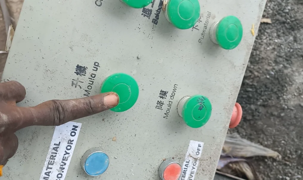
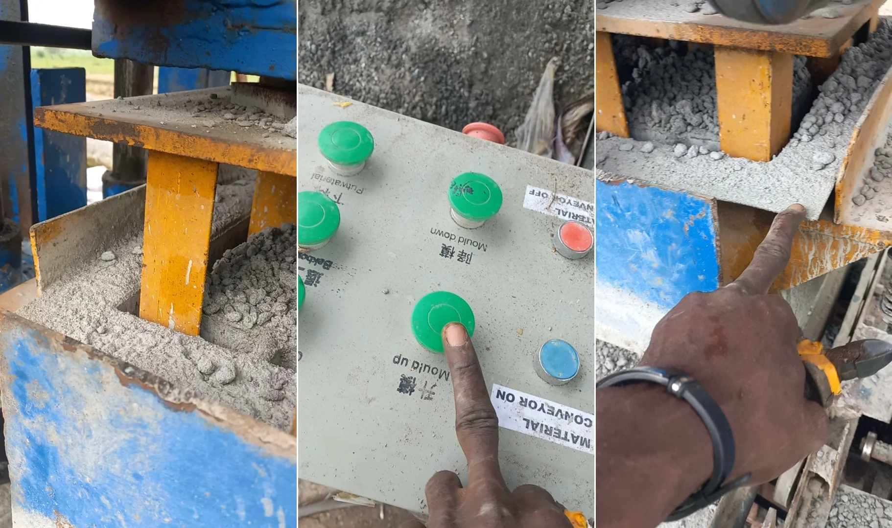
The primary issue was the failure of the "Mould Up" button on the control panel. This button is essential for the machine's operation, as it actuates the mechanism that lifts the mould after a block has been formed. Without this function, the production cycle is halted, leading to significant downtime and loss of productivity. The challenge was to identify the root cause of the failure within the intricate wiring of the control panel and the associated mechanical components.
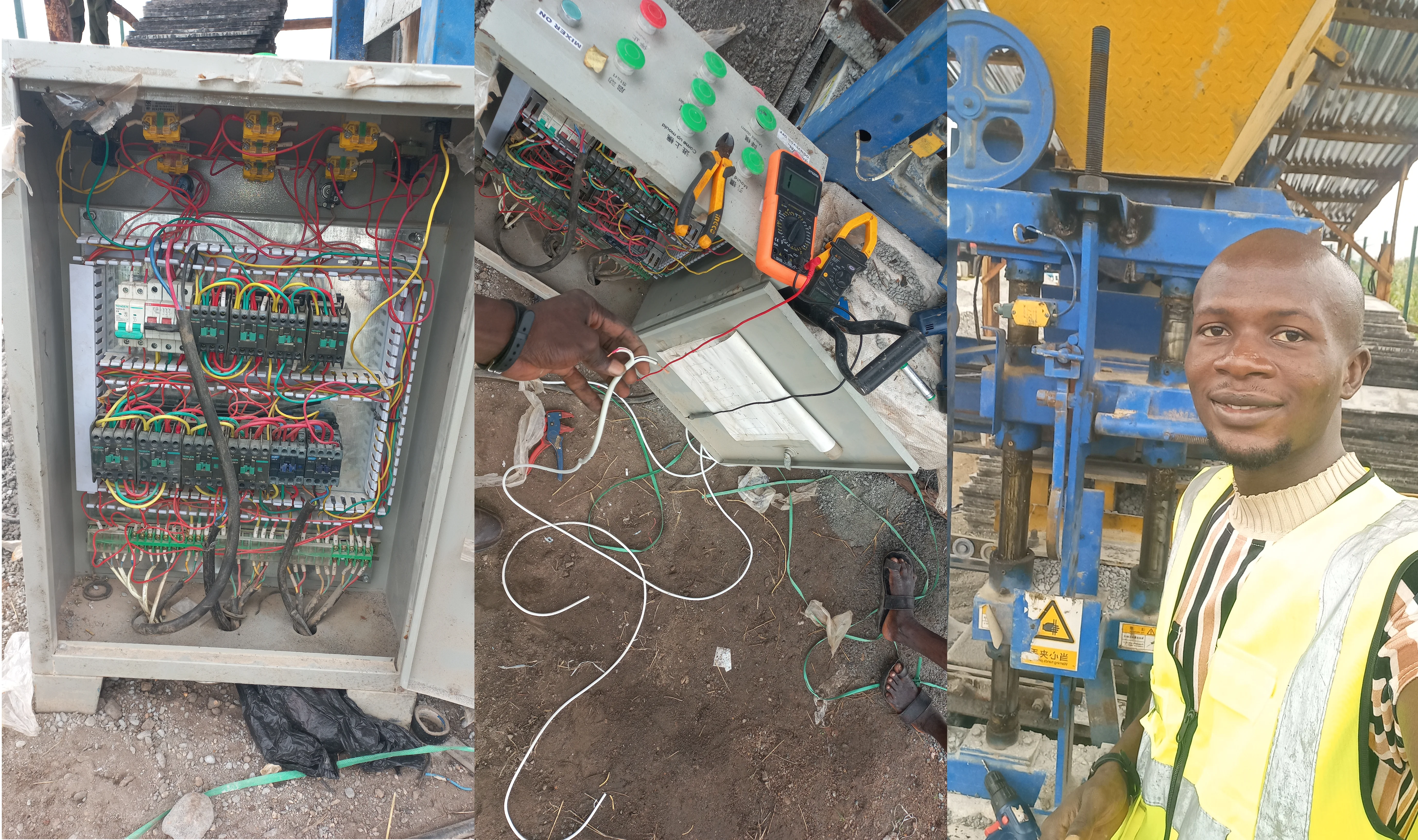
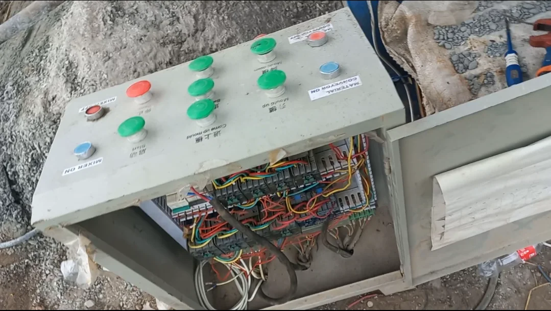
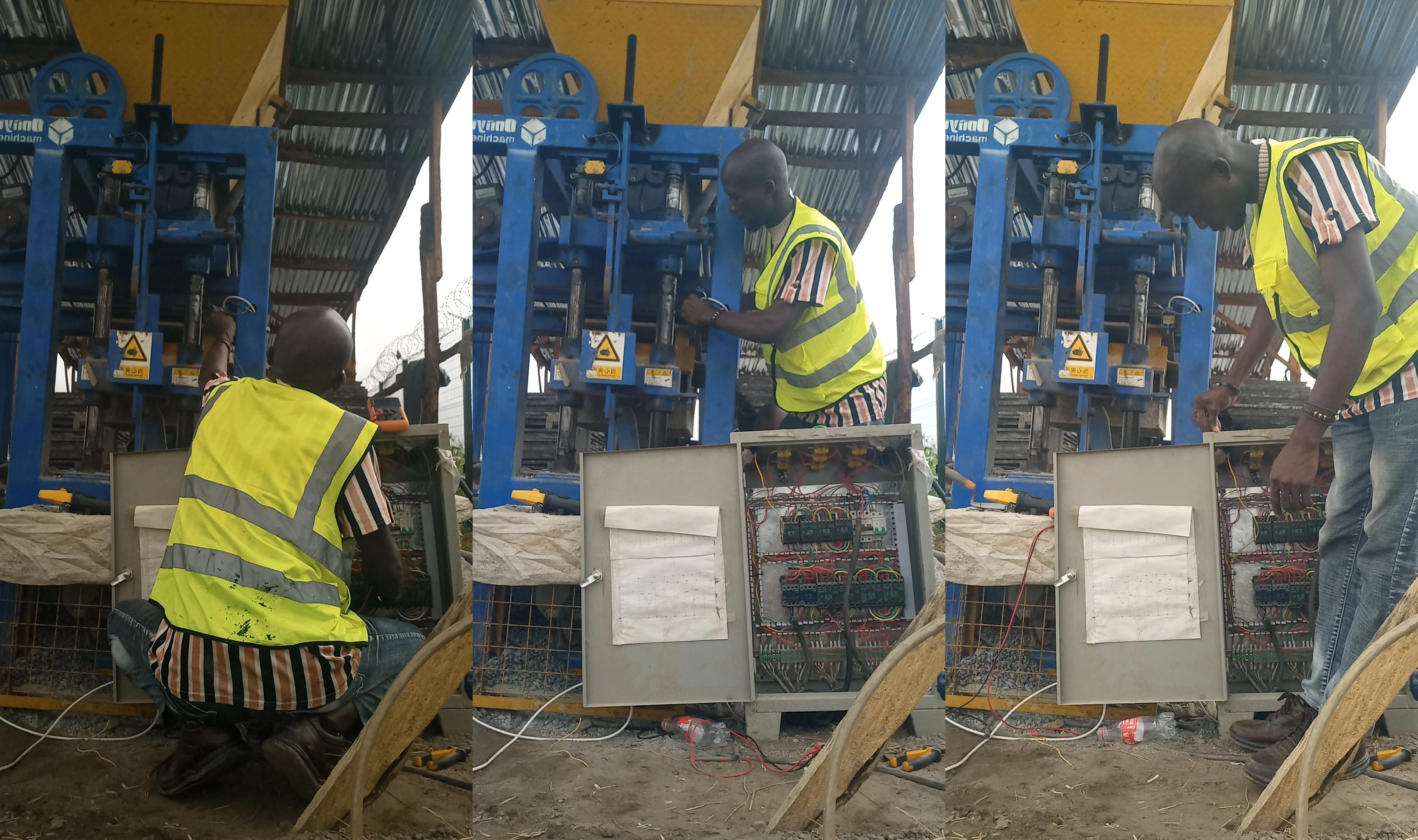
The QT4-24 Machine and its Control Panel
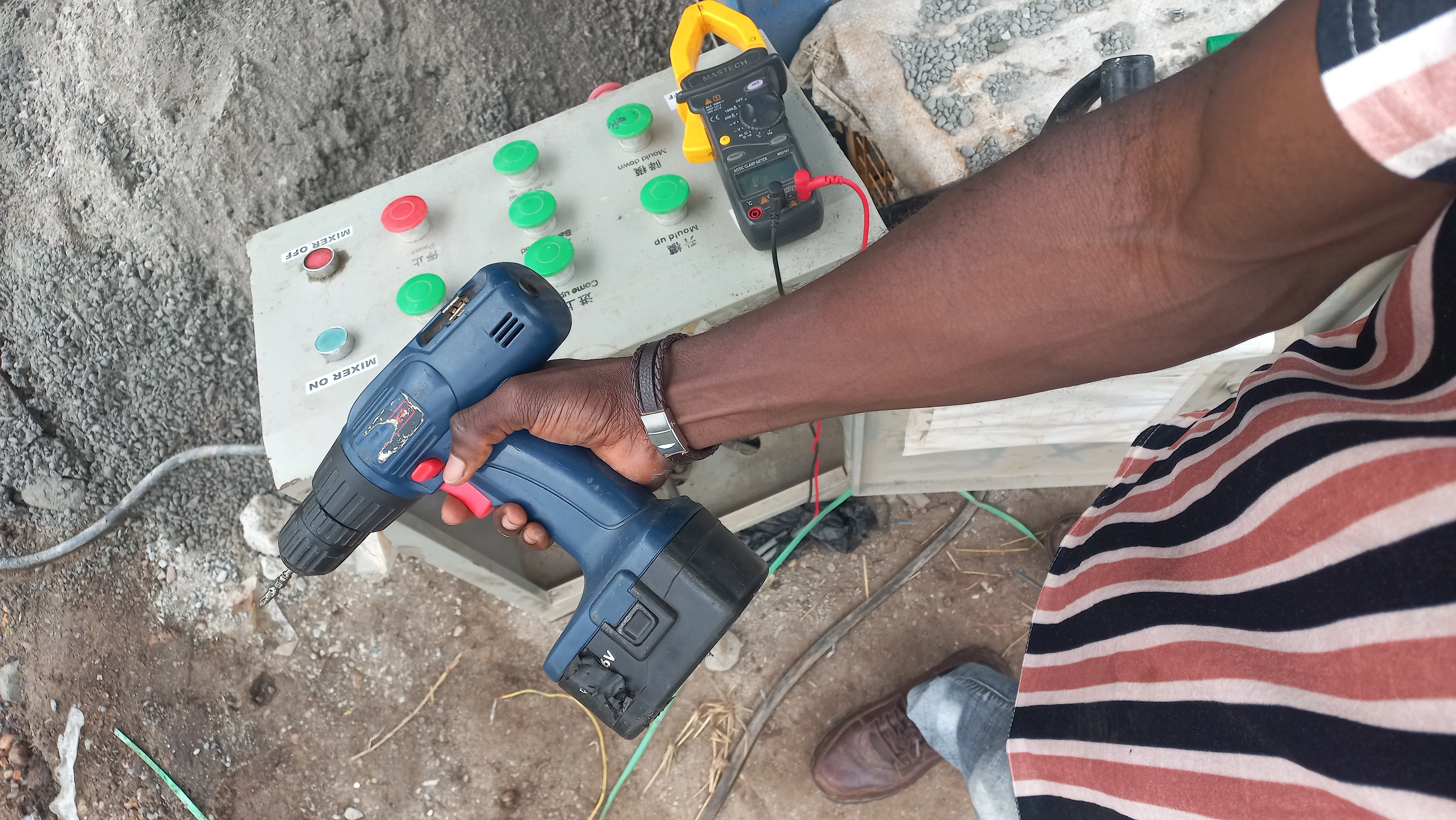
 The problematic "Mould Up" button on the control panel.
Step-by-Step Troubleshooting and Repair
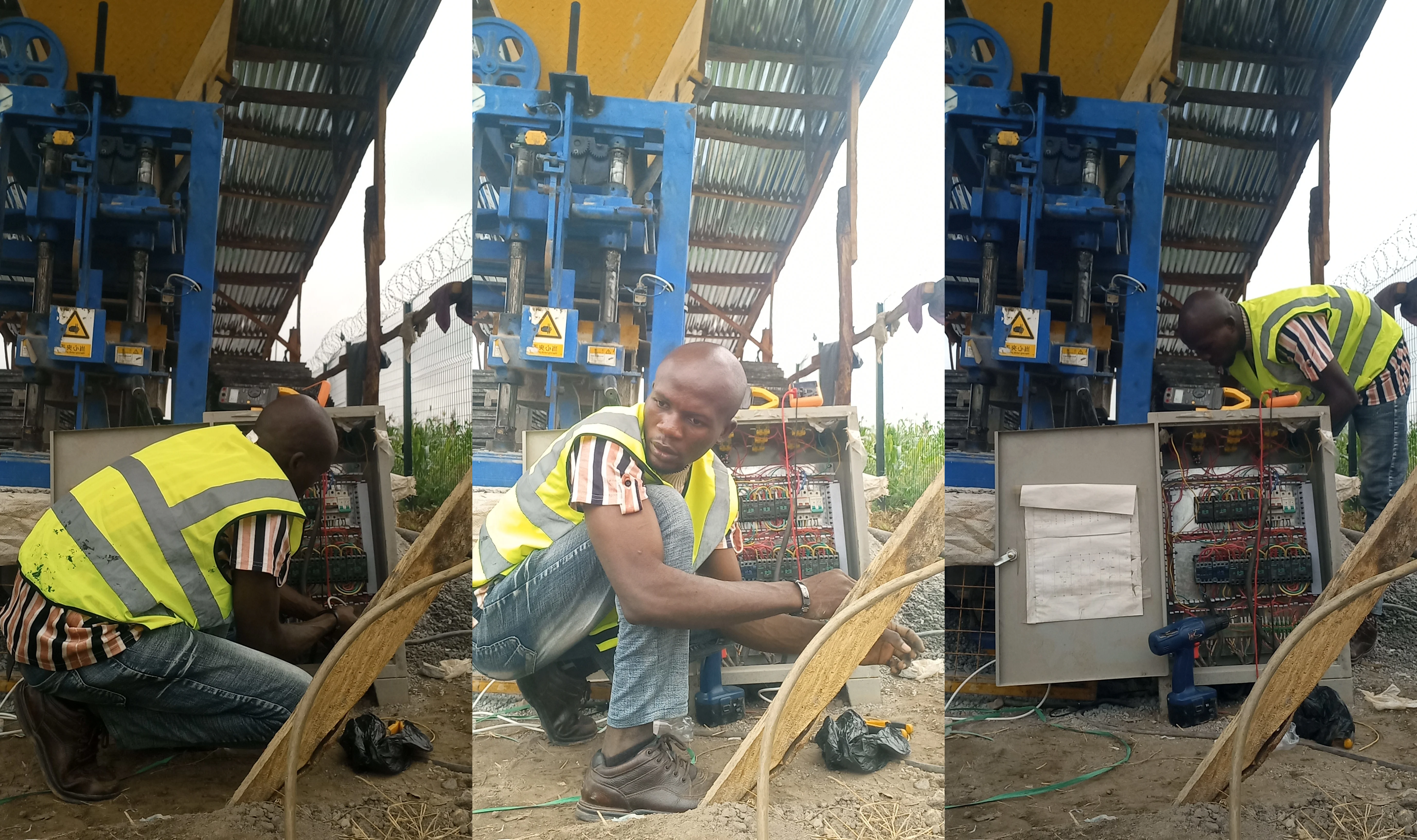
1. Initial Inspection and Tools
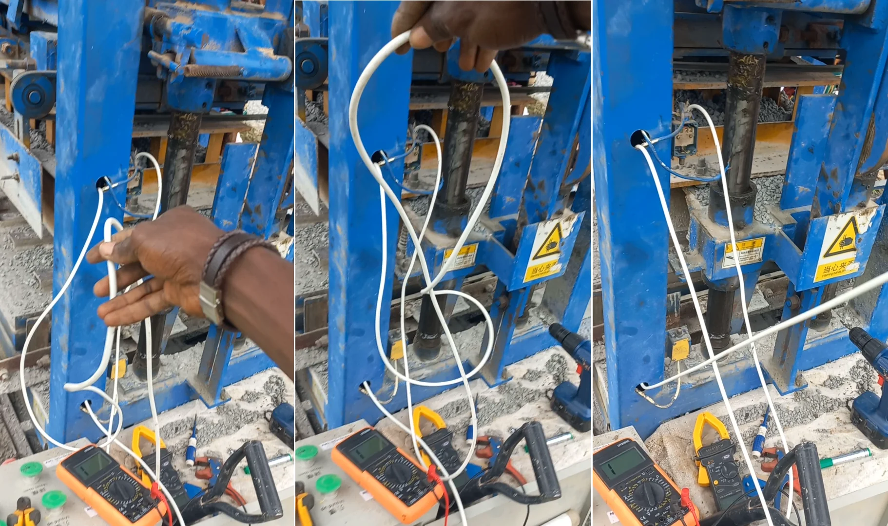
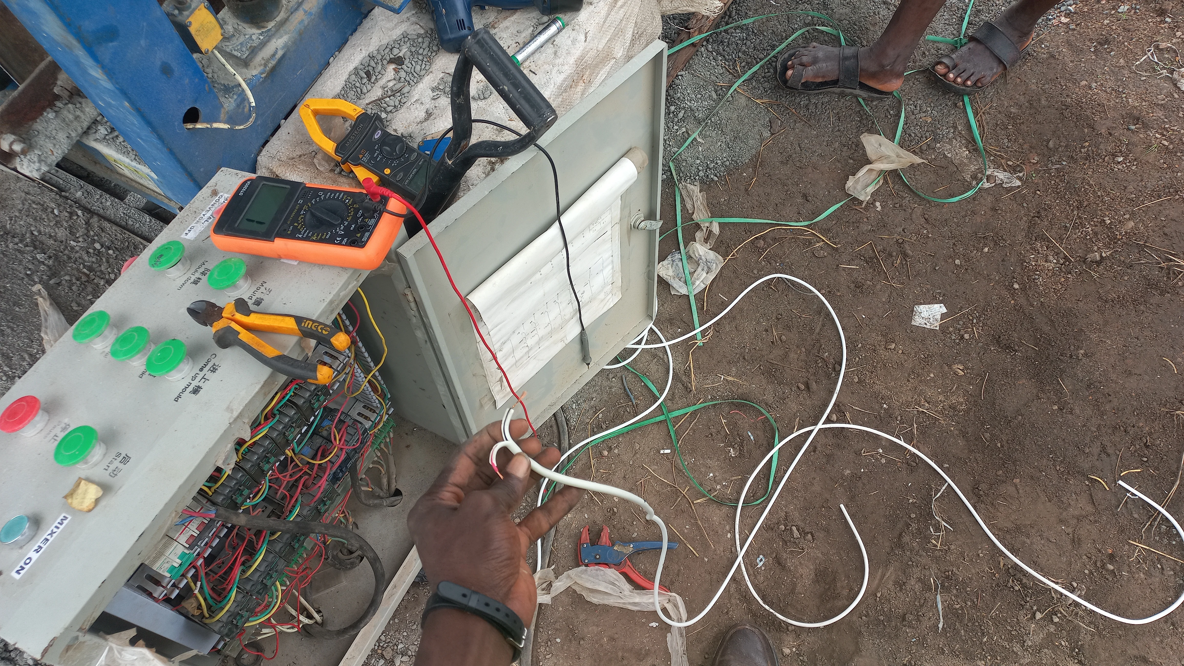
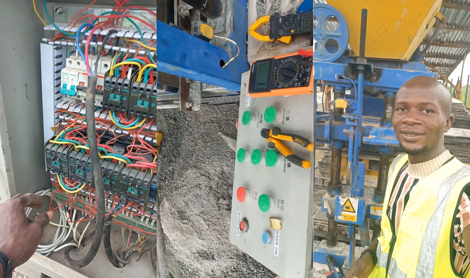
The repair process began with a visual inspection of the control panel and the relevant wiring. The essential tool for this task was a multimeter, set to continuity test mode to trace electrical paths and identify breaks in the circuit.
Preparing for the diagnosis with a multimeter and other tools.
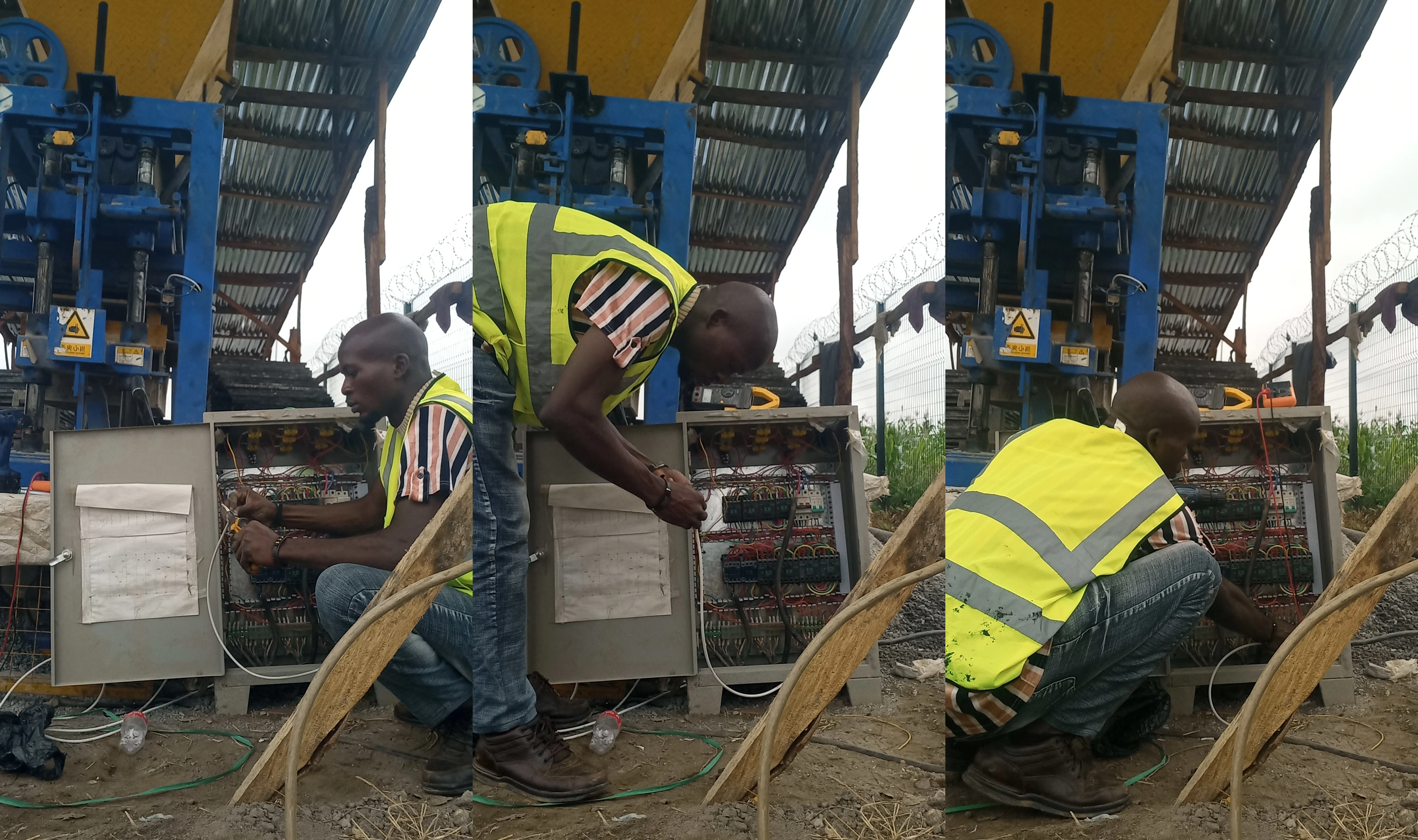
2. Tracing the Faulty Circuit
Using the multimeter, I began tracing the circuit from the "Mould Up" push button. The continuity test helped to verify that the button itself was functioning correctly. The trace then led to the wiring connected to a limit switch. Limit switches are crucial safety and control components that signal the position of a mechanical part—in this case, the mould assembly.
Using the multimeter to test continuity and trace the circuit.
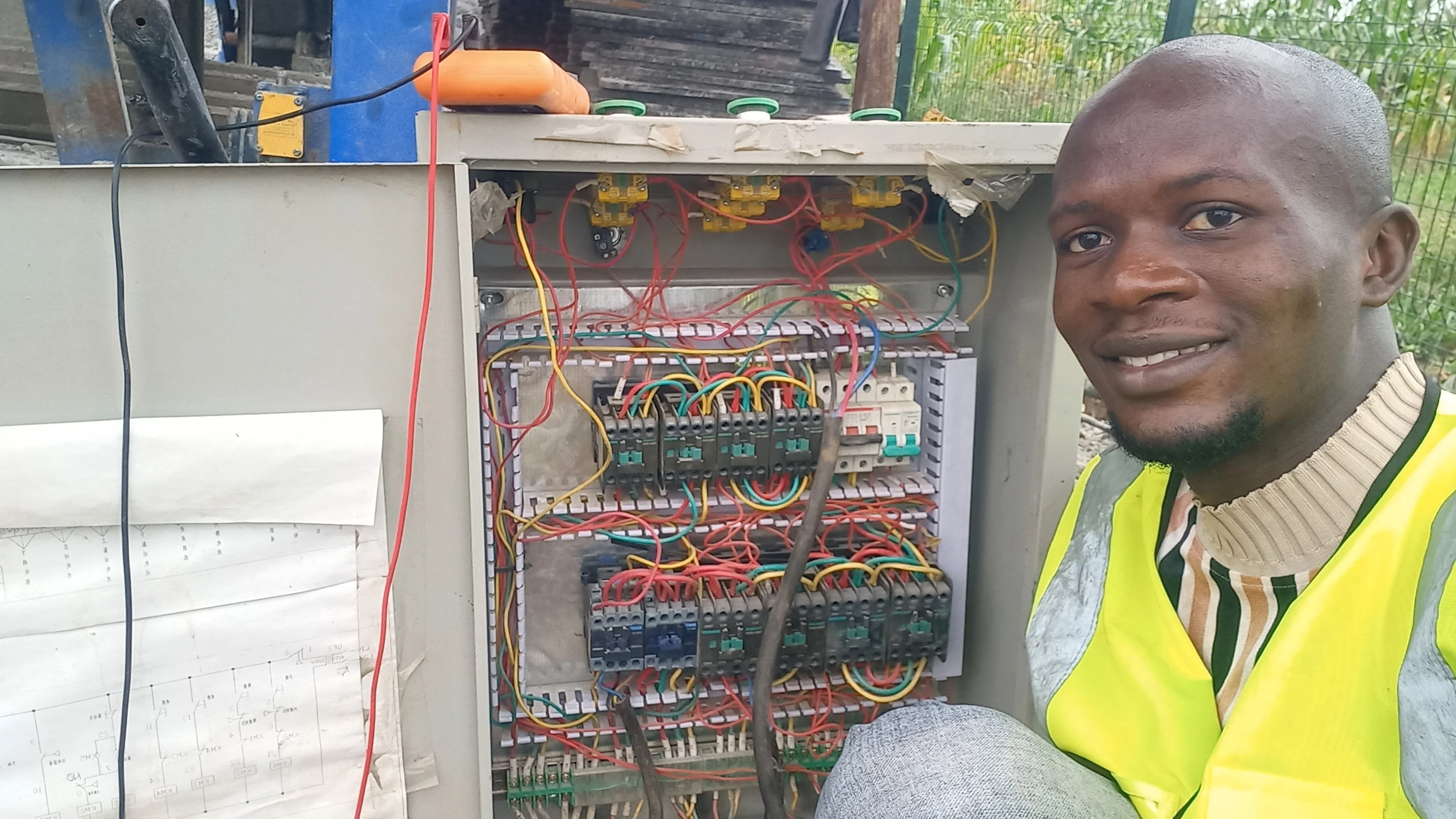
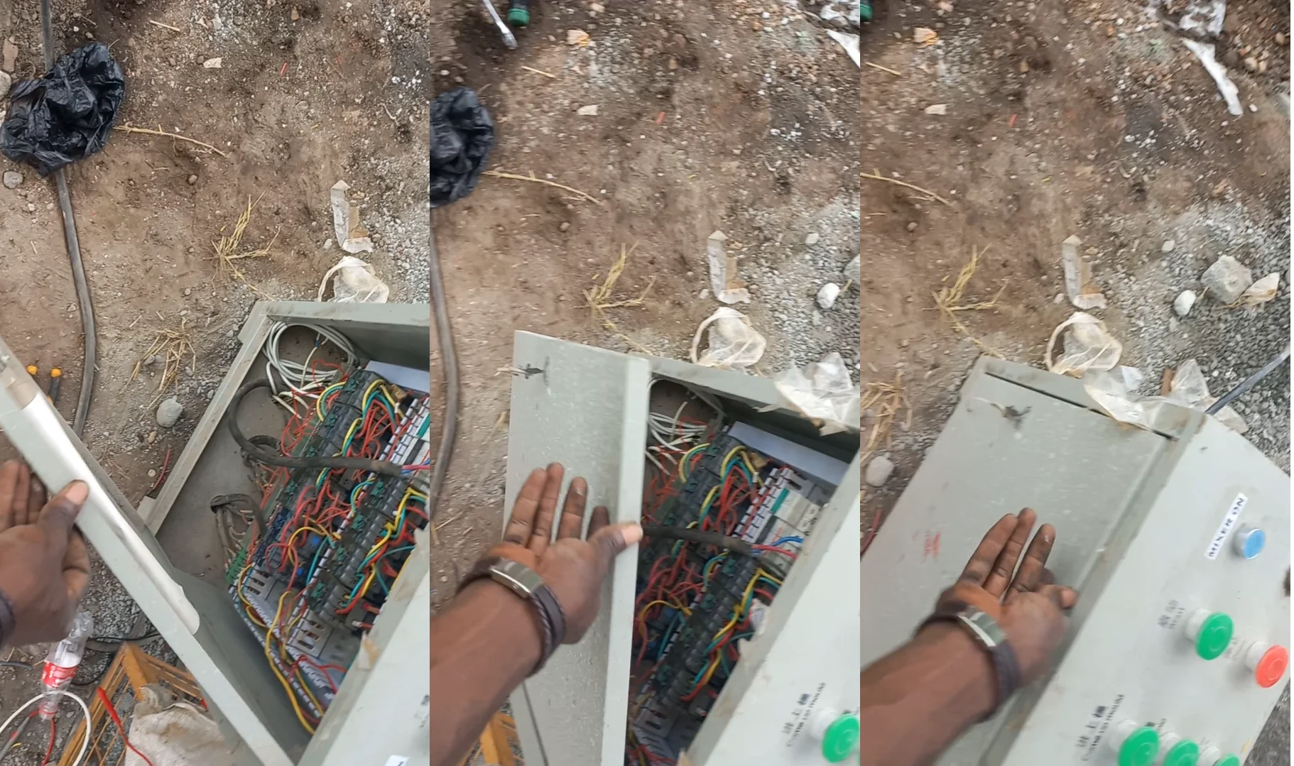
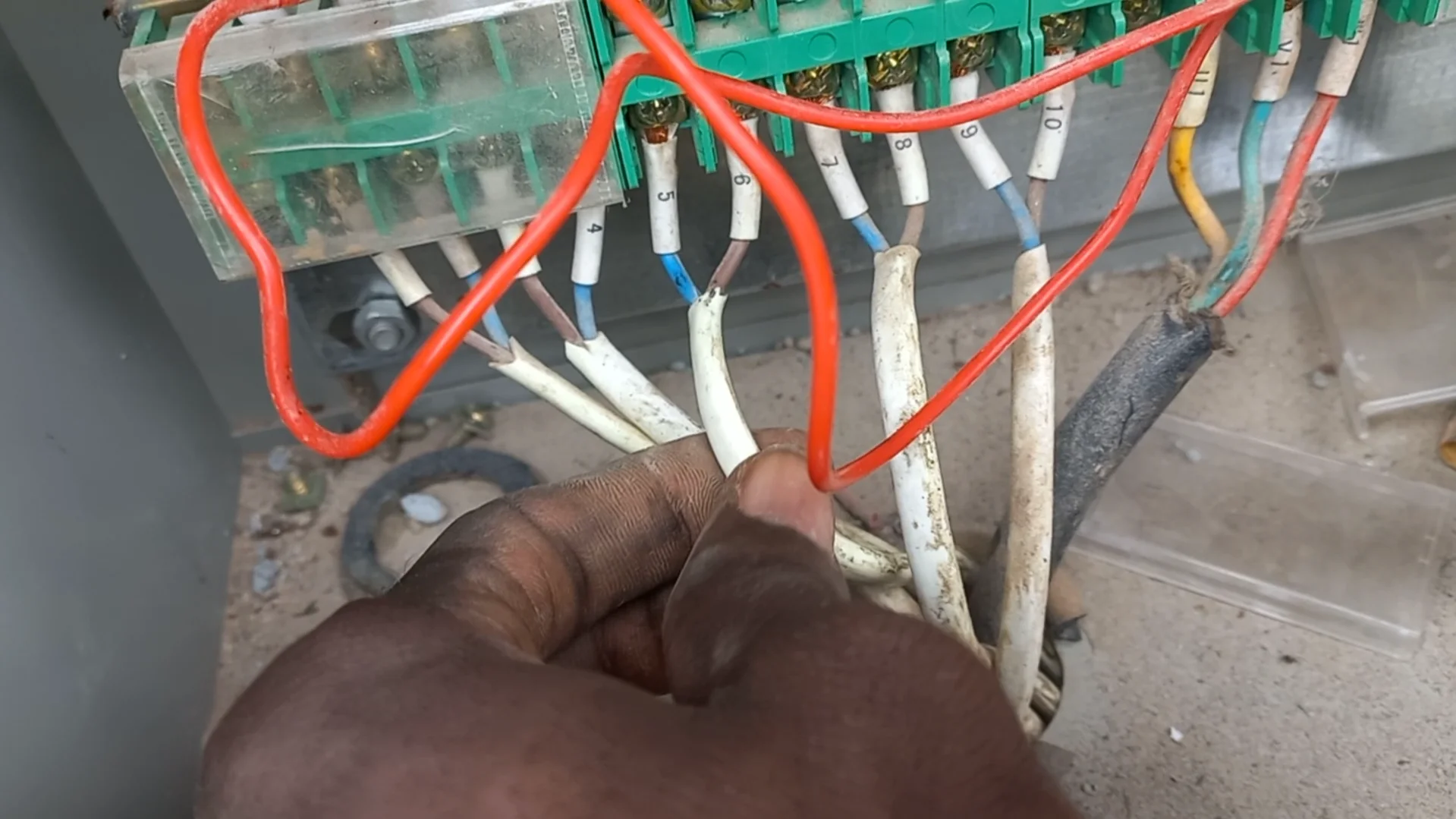
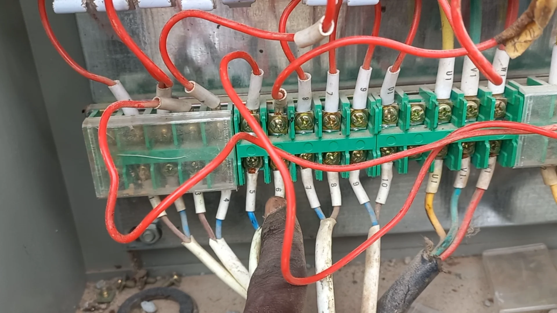
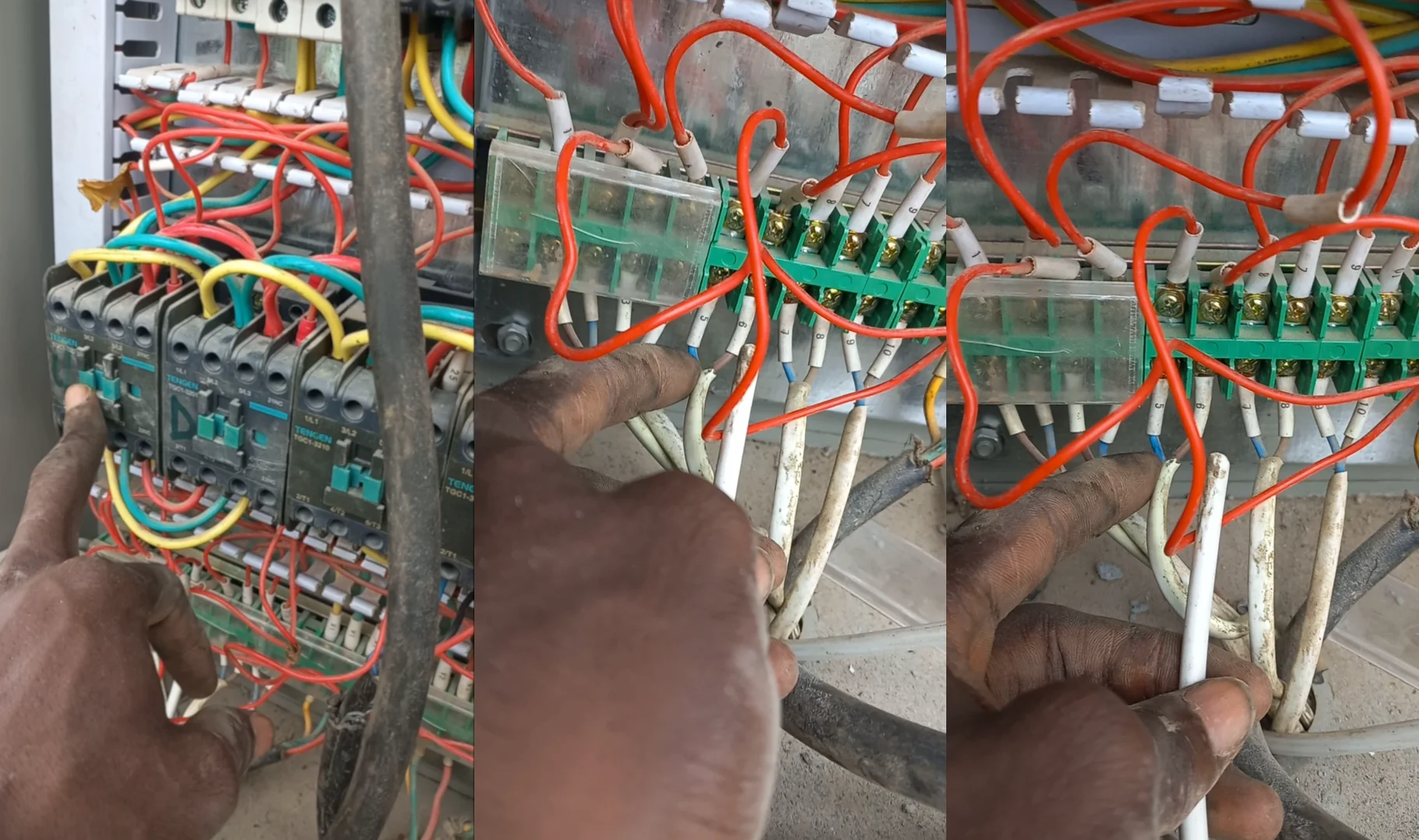
 Close-up of the control panel wiring during the trace.
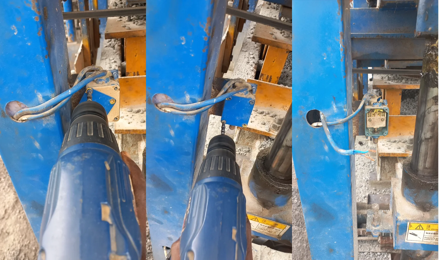
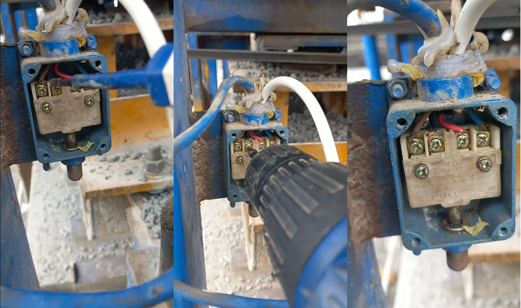
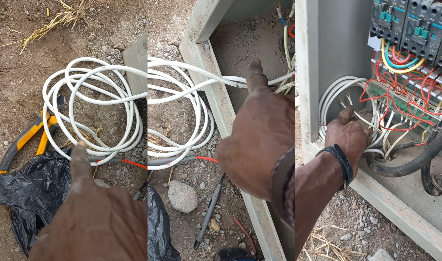
3. Identifying the Broken Cable
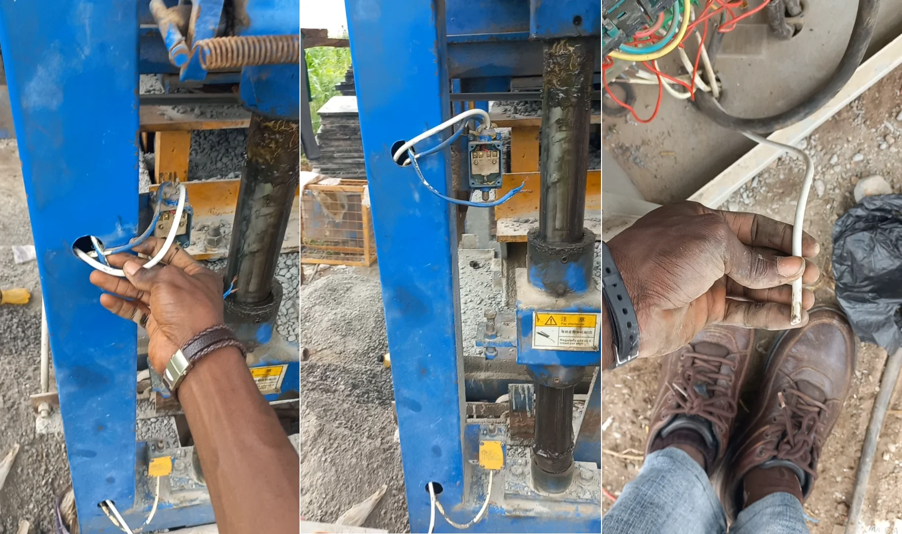
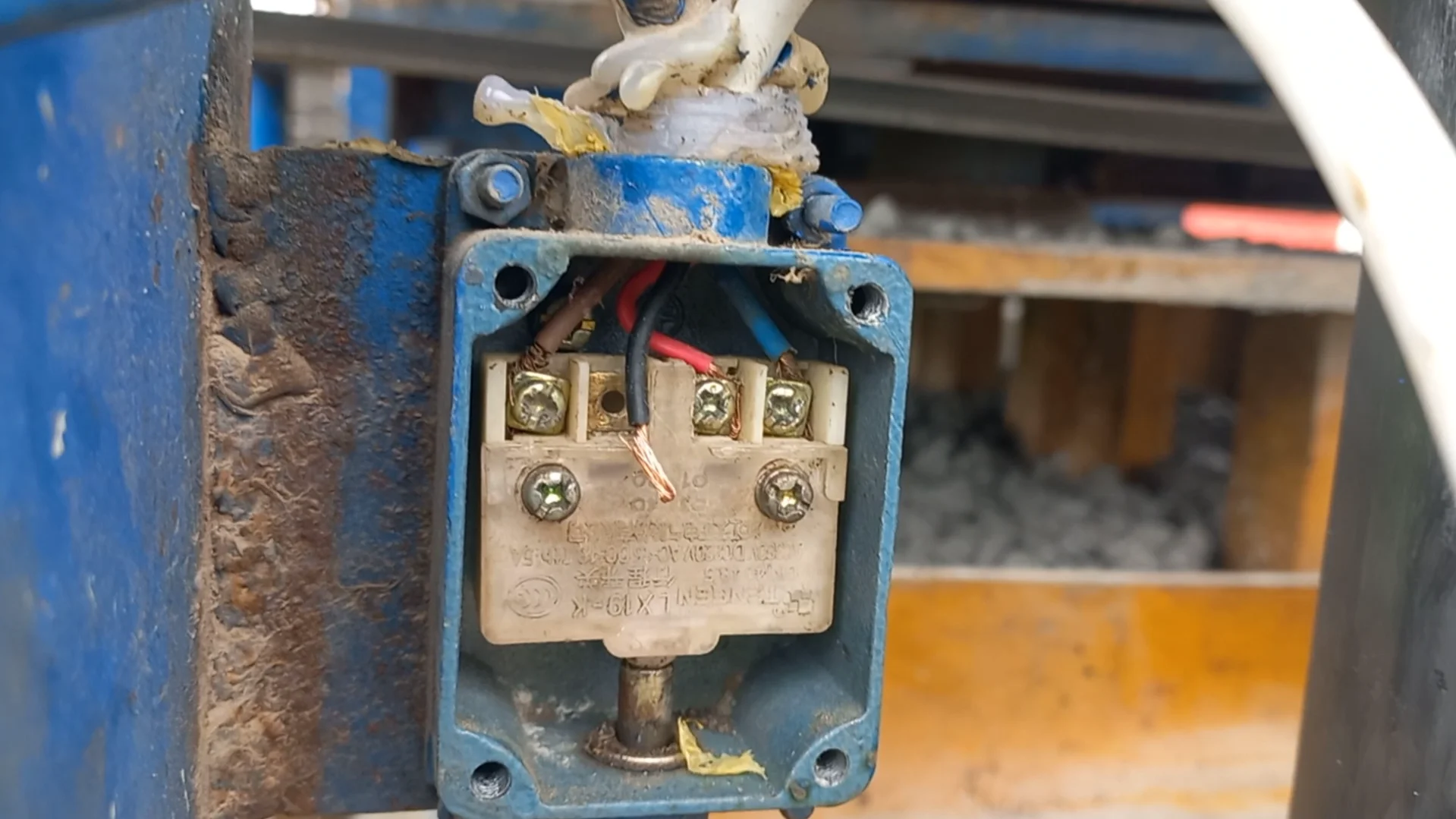
The continuity test revealed a break in the connection to the limit switch. Upon closer inspection of the wiring, a physical break was discovered in the cable leading to the switch. This broken wire was the root cause of the malfunction, as it prevented the electrical signal from the control panel from reaching the limit switch and, consequently, the motor responsible for lifting the mould.
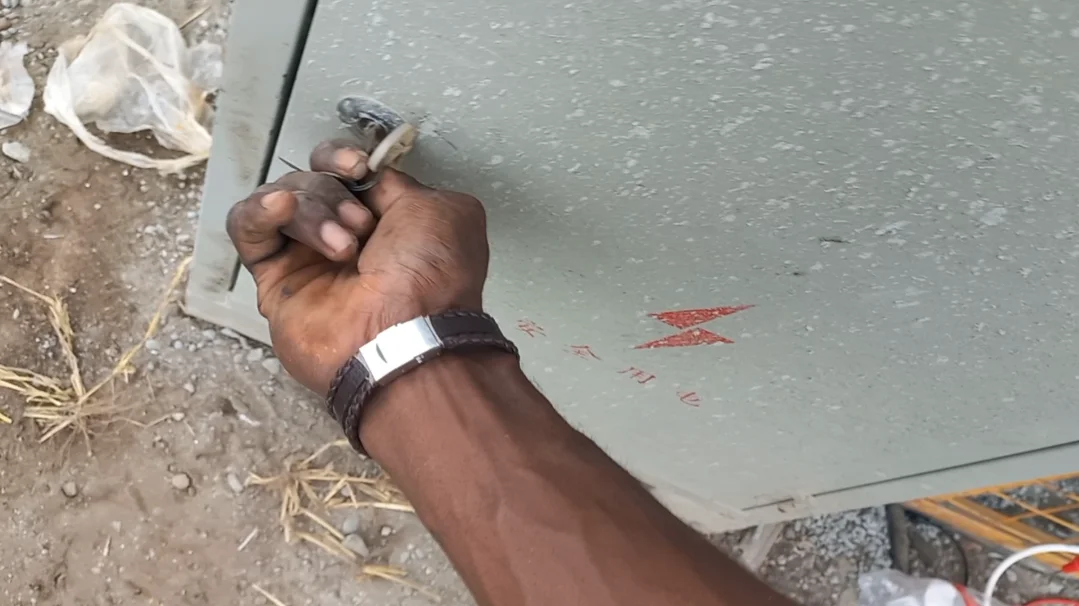
The broken cable with the faulty limit switch connection.
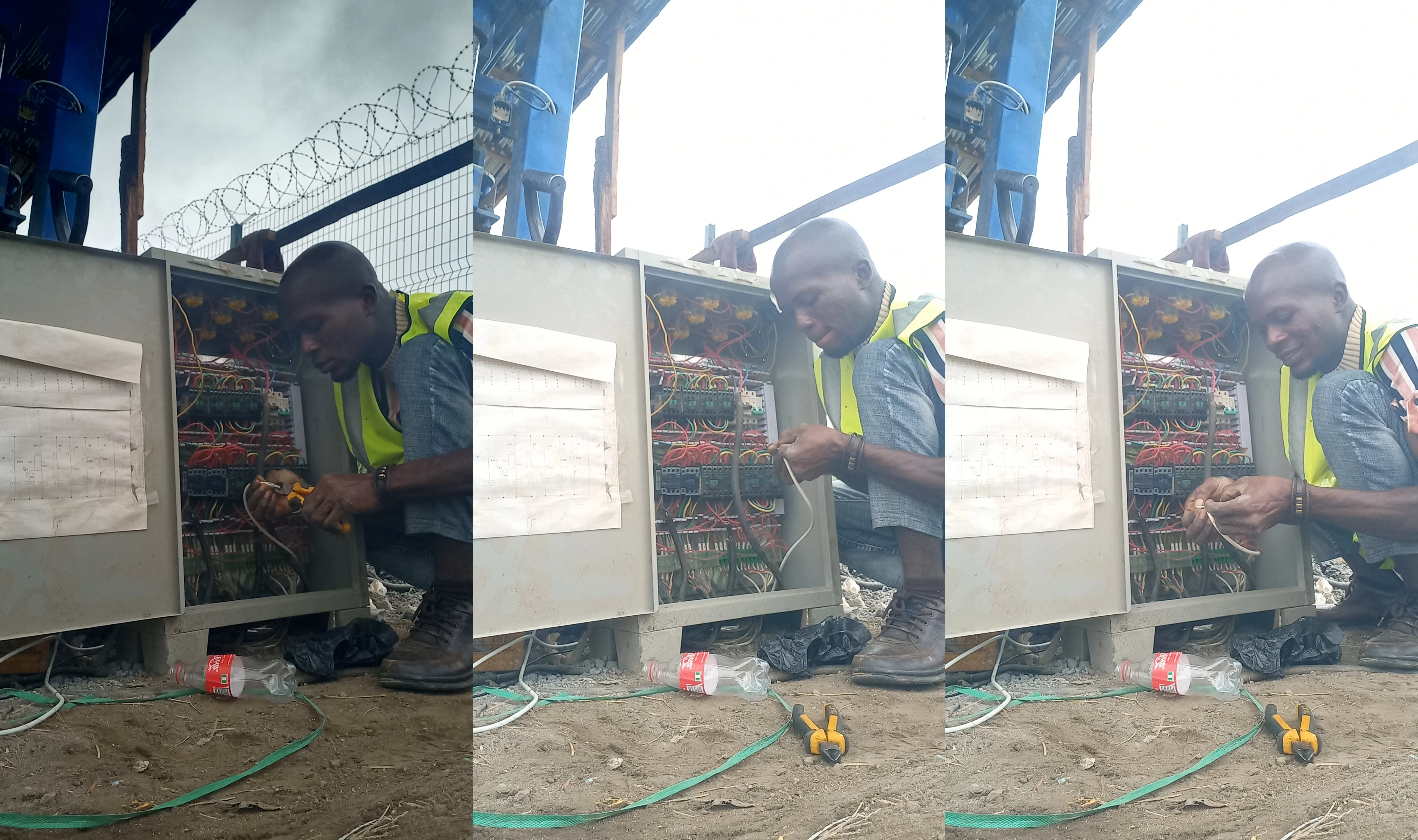
4. Implementing the Solution
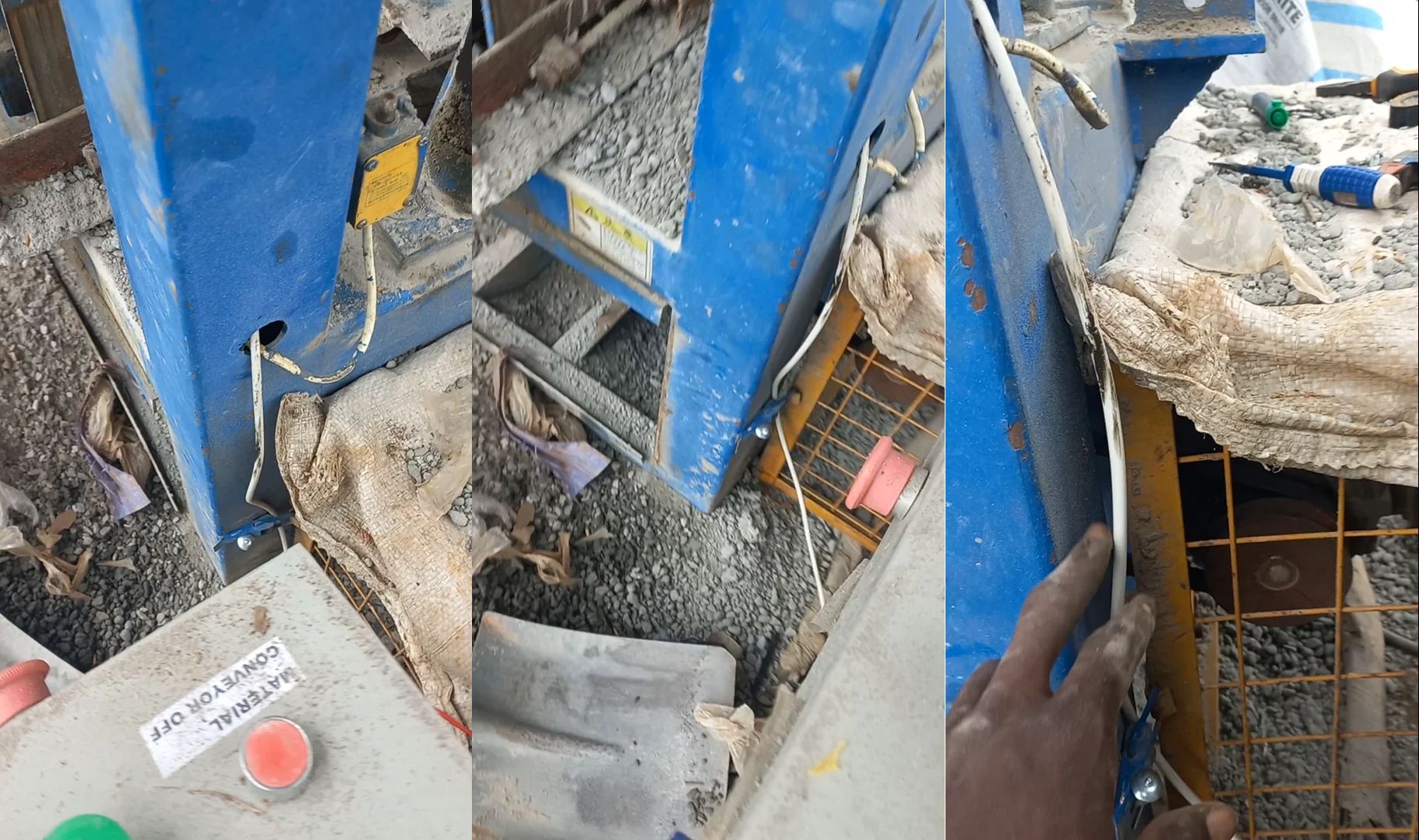
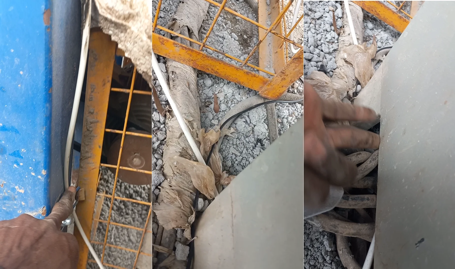
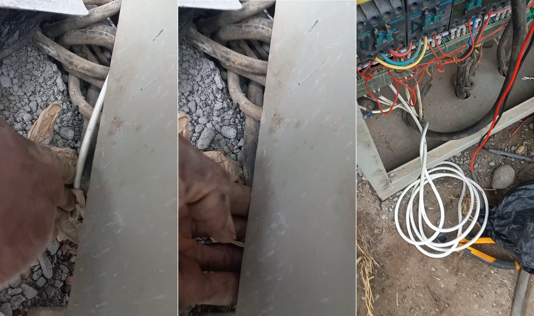
The solution was to replace the damaged wire. A new twin-core cable (with red and black wires for clear identification) was cut to the required length. The old, broken cable was carefully removed, and the new cable was run from the control panel to the limit switch. The connections were securely fastened to ensure a reliable and lasting repair.
Running the new twin-core cable to the limit switch.
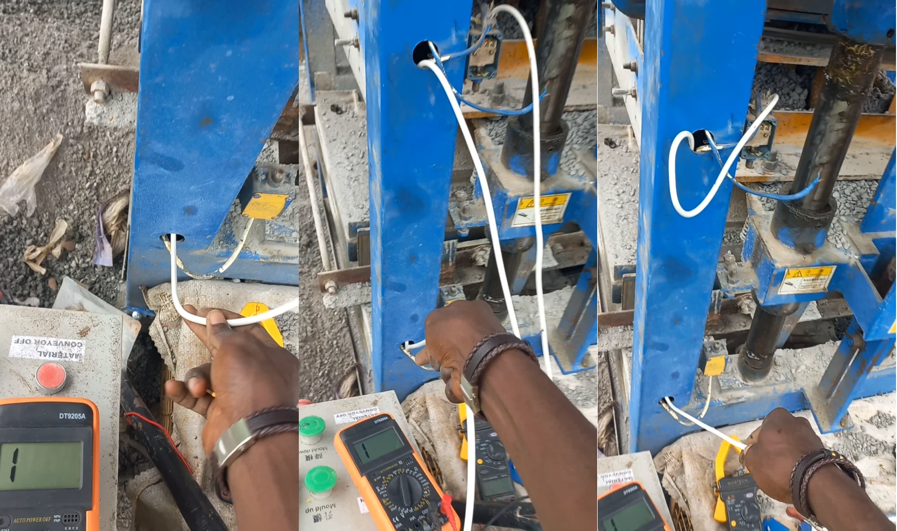
 Running the new twin-core cable to the through the ground to the control panel
 Securing the new connections at the limit switch.
 Stripping the cable and securing the new connections at the control panel's terminal.
5. Testing and Verification
After completing the wiring, the machine was powered on for testing. The "Mould Up" button was pressed, and the mould assembly responded immediately, lifting as intended. The repair was successful, and the machine was restored to full functionality.
Testing the "Mould Up" button after the repair.
Demonstration Video
This video provides a walkthrough of the entire troubleshooting and repair process, from identifying the problem to the final successful test. You can watch the embedded video below or click the link to view it on YouTube.
- YouTube Video: Watch the Full Repair Process on YouTube
What I Learned
- Reinforced my skills in industrial electrical diagnostics using a multimeter.
- Gained practical experience in troubleshooting and repairing control circuits for heavy machinery.
- The importance of systematic and patient tracing of electrical faults.
- Practical application of knowledge about limit switches and their role in automated systems.
Showcasing the Work and Expertise
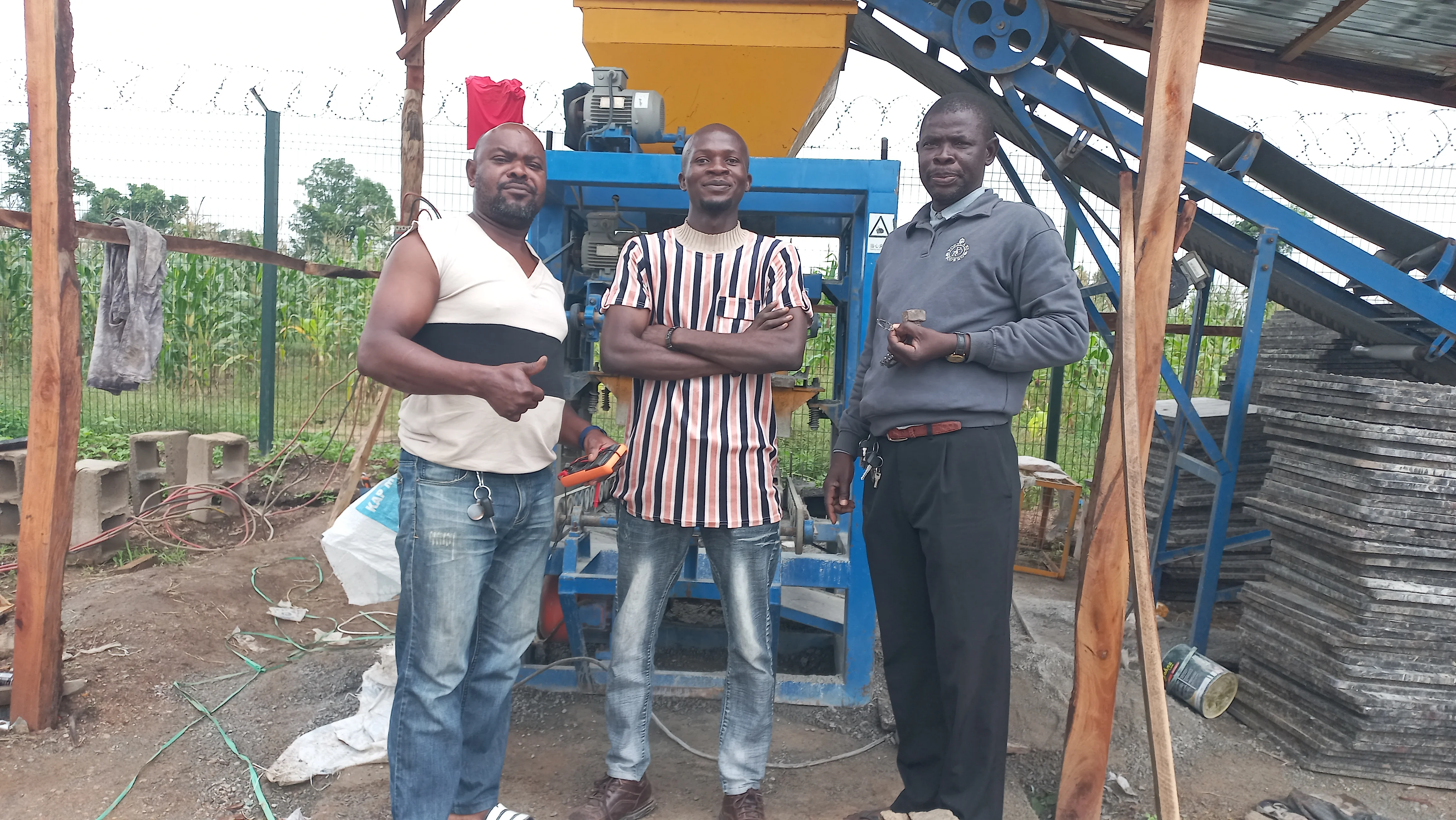
Thank You for Visiting My Portfolio
I sincerely appreciate you taking the time to explore this case study. It is my hope that this project demonstrates my hands-on approach to problem-solving and my technical capabilities in industrial electrical systems.
If you have any questions, require further information, or wish to discuss potential collaborations, I would be delighted to connect. Please feel free to reach out via the Contact section. Your feedback and inquiries are highly valued.
Best regards,
Damilare Lekan, Adekeye.